What is a CNC Router
|
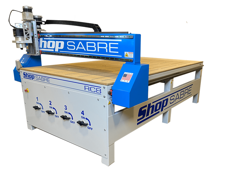
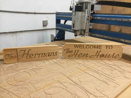
A CNC Router is a machine that allows you to cut sheets of wood, metal, or plastic. CNC which stands for Computerized Numerical Control, allows you to pre program the machine to cut the material in any designs you want using CAD (Computer Aided Design) and CAM (Computer Aided Machining). This machine can be used for many applications including hobby projects, furniture making, industrial use or making robot parts. It works by using drill bits to cut through materials at any depth and size. |
|
Kinematics
|
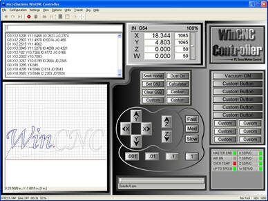
A CNC router moves linearly in 3 axis. Front and back in y, left and right in x, and up and down in z. It's speed is controlled from a computer manually when homing the machine, and automatically when cutting parts. Because you know its speed and position from the external computer, it is very easy to calculate acceleration, time, and displacement using the kinematic formulas. All the position based calculations on the machine are relative to the part so they can change between operations. You can use all of this information to create Position-time, velocity-time, and acceleration-time graphs to understand the movement of the machine by looking at slope, area and magnitude. |
Forces
|
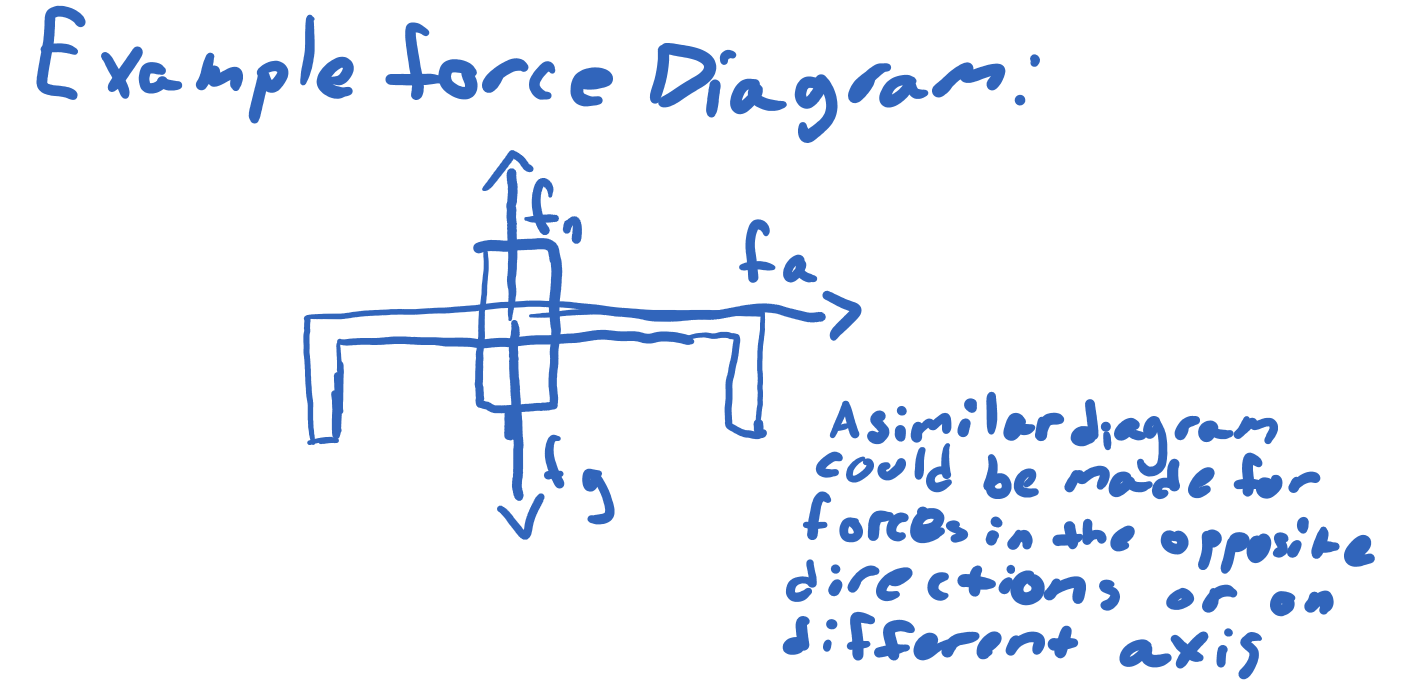
The forces on this machine are all applied by motors. Circular motion is converted into linear motion which moves the machine in all 3 axis. All of the forces in this system are applied forces. Though there is a gravitational and normal force, they cancel out. There are also no spring forces and any friction or resistance is negligible due to low friction wheels and rails. In this system we have multiple unbalanced forces that allow us to move the spindle in different dimensions and directions when the machine is moving. The system in this case would most likely be the spindle structure and blue cross bar which moves it. Understanding how forces work, you can use information like mass to find inertia, and Newton's Second Law Acceleration. You can also create a force diagram and system schema to help calculate the net force on the system.
|
|
Energy
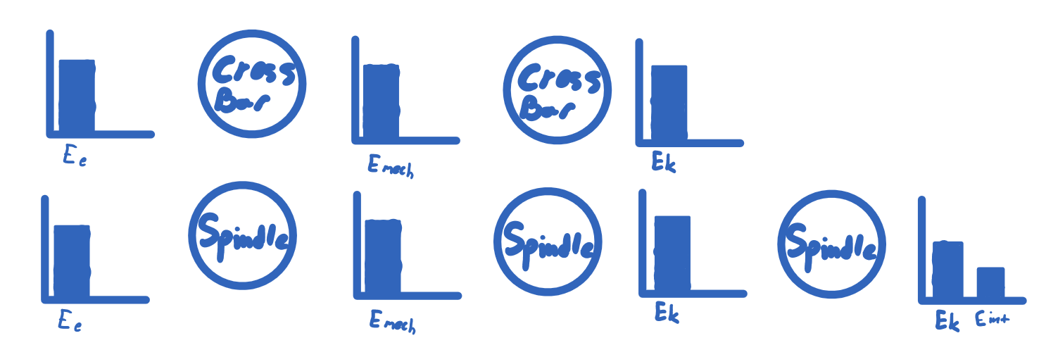
Energy is also assisting this system. In this machine there are multiple types of energy. Mechanical energy which is present in the motors is then converted to kinetic energy resulting in the linear motions of the machine. Thermal energy, which is caused by the friction made from the drill bit making contact with the material it is cutting. Energy transfers also take place in this machine. Energy is converted from electrical energy to mechanical to kinetic energy. For the spindle, the kinetic energy is partially transformed into internal energy caused by friction. These energy transfers can be shown in an LOL chart.
Momentum
Momentum, which is a vector, is the product of mass and velocity. Momentum can be seen in the motion of the main crossbar. The unknown mass of the crossbar system multiplied by it's manually set speed would be equal to its momentum. Angular Momentum or L is also present in the drill bit and spindle. The combined mass of the spinning system multiplied by it speed would give the angular momentum of the drill bit.
Rotation
Rotational Kinematics, Inertia and torque can also be observed on this machine. Using the equations for rotational kinematics it is possible to solve for the speed and acceleration of the spindle which holds the drill bit. The kinematic equations for rotational motion are very similar as those for normal kinematics the only difference being the change in variables. Using the right hand rule, it can be determined that the drill is spinning up. It is also possible to solve for the torque which is being exerted directly in the center of the bit. Finding the rotational inertia is difficult for such a weird shape like a drill bit. However with the right equation, you could determine the the inertia which tells you hard it is to change the acceleration of the spindle.
